School Automation System Component UML Diagram
Table of Content
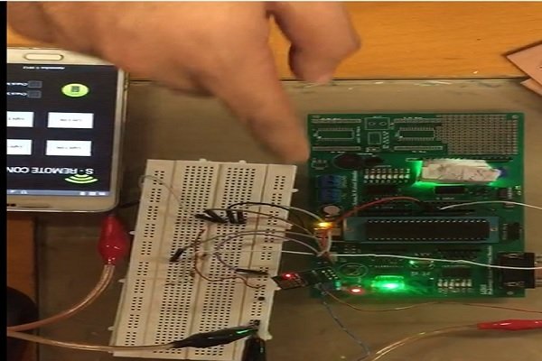
Make sure the circuit is connected to the power supply and the Bluetooth module is on. Also, make sure the Bluetooth module pair with your smartphone. You can pair your phone with the HC-05 Bluetooth Module like we normally pair the phone with Bluetooth earphones or speakers. Here you can see the Buttons and a mic symbol for the Voice command.

We will need a variable to store the message received by the HC-05 module, and variables mentioning the pins to which the LEDs are connected. How to prevent calls from other mobile and mall functioning of DTMF decoder as any one can dial mobile connected to circuit. Can we control home appliances using dtmf tone, through wifi lan connection...if yes then please send me a solution, that how it will work..
Lighting Control
6 analog input channels are from pins A0 to A5 and provide 10-bit resolution. The board can be powered either from using a USB cable which operates at 5 volts or by DC jack which operates between 7 to 20 volts. There is an onboard voltage regulator to generate 3.3 volts for operating low powered devices.
There’s no need to fight over control of the thermostat anymore. Installing a smart thermostat will give you complete control from anywhere. You can program the thermostat to save energy when no one is home and spring to life before you get back. Using an app, you can lock the temperature controls to keep the kids from blasting the AC on a hot day.
Simulation program
The Ring doorbell is gaining in popularity because it lets people see who is at their door without having to open it. The videos catch porch pirates and record car crashes that are used later to catch criminals. Join over thousands of organizations that use Creately to brainstorm, plan, analyze, and execute their projects successfully.
These specifications make Arduino Uno board perfect for Home Automation project. We’ve discovered that pressing each key on the keypad produces a tone that is distinct from the others. As a result, this DTMF encoder can be found in mobile phones. The DTMF decoder IC HT9107B may convert keypad output to digital format.
can we drive a electric fan
This is mini project in html with source code and database. The main purpose for developing this project was to create a static website for the School, from which user... Entertainment gadgets and electronics are usually the first things to get an upgrade. TVs, speakers, tablets, and streaming sources are all connectable. It’s possible to connect it all and watch all your programming anywhere in the world.

Your big-name voice assistants can be used as home automation hubs. If you purchase a home automation system, the hub will be included. And if you are a techno-geek looking to build your own system, you can buy a hub or convert an old laptop or smartphone. Home automation technology might not yet be at the point that the futurists of 50 years ago expected, but it is well on its way. Emerging technologies are making modern homes smarter, safer, and more efficient with each passing day.
Working of Arduino based Home Automation
In this component diagram tutorial, we will look at what a component diagram is, component diagram symbols, and how to draw one. You can use a component diagram example below to get a quick start. Include the libraries required for the project, SoftwareSerial.h library is imported for serial communication with Bluetooth Module HC-05. Today’s home automation systems are more affordable for more people. Systems can be integrated with monitored security or act as stand-alone systems.
Are you planning on a visit from out-of-state family members during the holidays? Give them a security code to unlock your front door and they can let themselves in while you are at work. Have alerts sent to your phone or e-mail and you’ll know they have arrived safely. Imagine a smart lock that allows your kids in the house after school without giving them keys.
But this time the Arduino sends a High input voltage to the Input-1 pin of the relay module. So the Light will also turn off, which is connected to the relay-1 of the relay module. At the same time, the “D1 is Off” status print on the 16×2 LCD Display Module. Then the Arduino gets this value through the Bluetooth module. Then the Arduino sends Lowvoltage to the Input-1 pin of the relay module. So, the Light will also turn on, which is connected to the relay-1 of the relay module.

But our operation has been performed because Q1 is LOW in key 8’s output and rest of appliances not affected. Now is we want to turned on FAN so we need to press key2 because by pressing key2 only Q2 is activated and rest of output are remain same. Now if we to OFF the FAN then we need to press key8 again like before for as LIGHT. Now if we want to TV so we need to press key4 and for tuning it OFF we need to press 8 like before. Now suppose we want to turned ON all of the appliances so we need to press key7 and for turning OFF all key8 .


Comments
Post a Comment